Monday, May 05, 2008

Harken Roller Furler

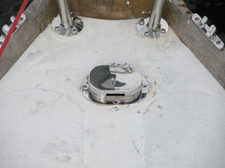
The boat came with this Harken roller furling system. I am posting these pictures mostly so I can show them to the sailmaker. But for what it's worth, here are some close-up shots of the roller furling system. I don't really have much to say about it other than that sometimes when I try to roll the jib with the spinnaker up I get halyard wraps, which are the bane of my existence. I HATE halyard wraps!


Rigid Boom Vang

Another rigging upgrade that I installed is the rigid vang. I got this from Garhauer at the boat show in 2006 (maybe 2005?). They made a template of my mast & boom and made custom collars to make sure they fit the spars, which was really cool. The vang works great. It doesn't fully support the boom with the full weight of the sail while furling, but it keeps it from crashing into the cockpit until you can get the topping lift on. It is very powerful so makes it easy to control the leech tension of the sail underway. When the main is up and going downwind, it does a good job of holding the boom at a reasonable angle and keeping the boom from closing the leech down too much in light airs. It is a really nice feature. Not as nice as a real traveler, but still nice nonetheless.

Engine Panel

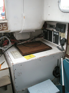
This is a shot of my recessed engine panel. This is the Beta type 'C' panel. I bought the recessed setup from SSI Custom Plastics. Here is a link to the actual item: http://www.ssicustomplastics.com/everything.htm. It's item # 47800000. I installed it where the A4 panel had been. I really like having the recessed panel because before people were forever kicking the switches & gages on the A4, and having the panel recessed really reduces that. Also, it had room for the fuel gage and the water washdown outlet (more on that in a later post...).

I just like having a nice, neat, recessed engine panel installation. It makes me happy.

Two New Stanchions

Originally, when I bought Calliope, she was fitted with a boom gallows which was a silly apparatus. Basically this was a stainless structure that went over the cockpit and supported the boom. What it also did was prevent you from trimming the main properly. She also was fitted with ratlines but we won't even go there. Anyhow, the boom gallows was something that I removed relatively soon after buying the boat, but this left a gap at the cockpit where the lifelines would be unsupported so I needed to buy some stanchions. My 'quick fix' for this entailed going to bacon's and buying what they had. I got 2 stanchions with circular 4-hole mechanical bases and installed them. This system worked fine for 4 years, but it was less than ideal...they were not very stiff, the mechanical bases were not so great, they were 7/8" rather than 1" like the other stanchions, and the collars I was using did not hold the lower lifelines properly. I got new lifelines last year which have pelican hooks for the end attachments so that they can be opened at the cockpit, forming a 'gate' which makes it easy to load and unload things at the cockpit...super nice.

I decided that it was finally time to replace these stanchions so I bought some with welded bases off the rack at Tops in Quality. They sold me these for $40 each which I thought was quite a good deal. They don't exactly match the other stanchions but I don't care too much and they are very stiff. I also got some gate braces from Bacon's which fit them nicely. Installing them was a bit tricky as the bases have no angle to them but the stanchions could not be installed perpendicular to the deck or they would be sticking waay out. So I had to make some wedges for their bases which allows them to stand at the proper angle. I ordered some plastic splitting wedges from McMaster which I cut out to form base wedges of the proper angle to fit the stanchions on. While I was at it, I fabricated some backing plates from 1/4" G-10 which would make them nice and stiff. When I marked the holes, I overdrilled them with a 3/4" forstner bit, and backfilled these oversized holes with thickened epoxy. Then after the epoxy cured I drilled & tapped 1/4" x 20 TPI holes for the fasteners. I installed stanchions, wedges & backing plates in a generous bed of polysulfide caulk. Christina helped me to tighten the through bolts which was very nice of her.

After I had attached the stanchions I installed the gate braces at the proper angle and I also attached bushings which hold the lifelines forward of the stanchion under tension even when the gate is open. I am very happy with this system. These stanchions are much stiffer and they look better than the old ones too! It's nice to be able to open the gate without the whole lifeline going slack!

Here are some shots of the new stanchions:
This is what the big picture looks like. Note the gate brace and strop bushings on the lifelines. This is a close-up of the base where you can see the plastic wedge under the stanchion.
This is a view from the underside that shows the bolts (a bit too long) along with the 1/4" G-10 backing plate.

Binnacle GPS

The binnacle in the bridge deck has never been useful. You can't put a compass there because it's too close to the engine for the compass to work properly. I have been trying to figure out a way to use this space since I got the boat. I thought about cupholders but could never make that work. I thought about glassing back over it and recovering the space inside the boat. Never did that. Then I found that West Marine was having a sale on GPS chartplotters, and I got this one which fits PERFECTLY in the space for the binnacle. I had to make a (minor) modification to the mount bracket in order to get it in there, but it worked, and it's awesome. I got an external antenna for it which lives on the stern pulpit and it is plumbed right into the boats main power system (on the electronics bus). It works great. We used it for navigating out of Cantler's at night last weekend and it was phenomenal. It has a nice RS-232 interface that allows you to plug it into a computer to upload/download maps and routes. And I *think* that I can get it to interface with my other instruments, although I'm not 100% sure about that...yet.

Stoked on this upgrade!

Mast Beam Reinforcement

At the 2007 Maintenance Seminar, with a good deal of help from Mike Lehman, I re-did my mast beam. Unfortunately I don't have pix of the old reinforcement, and I don't have pix of what the beam looked like after we removed the old reinforcement. But the main thing is I only had one aluminum plate (on the aft side) which was clearly not sufficiently strong to carry the load because the beam had sagged to the point where I could not close the hanging locker door anymore. So I realized that I needed to reinforce the beam with the 'official' fix which is to have 2 aluminum plates sistered on either side of the original beam and through-bolted. I had these plates made at a machine shop up in Baltimore. I think they were about $400 or so. Mike and I drilled holes in them, etched them with acid, epoxied them to the original beam, and through-bolted the whole mess. We did this after loosening the rig and jacking the main beam back up into position.

Mike was hugely instrumental in completing this project. It was a HUGE job, much bigger than I had anticipated. Without Mike's help I never would have got this done. One funny story is that just before we were going to etch the plates, Mike dropped one in the water and I had to go swimming to retrieve it. Only afterwards did he tell me that they had a water treatment facility overflow into their creek last year. No wonder the bottom was so soft and slimy... ;-)

Here are some pix of the results:
Looking forward at the main beam in the head. You can see the teak vertical support that Mike added to carry additional load.
Looking aft at the port side of the forward beam in the forward compartment.
Looking aft at the starboard side of the beam in the forward compartment.
A close-up of the aft side of the beam in the head, looking forward.

Bow Pulpit & Anchor Hawse

A couple years ago when I still had the dying Atomic Bomb, I had hit the SSA dock while coming alongside singlehanded and the engine was acting up on me. I wasn't going fast but it was enough to bend the pulpit significantly and really messed the pulpit up. Last year I tried to salvage it by having some new forward supports made and applying some brute force to bend it back into shape but ultimately it was just not to be and after sailing for a season with one of the mechanical terminals refusing to stay connected or be bent back into shape, I decided that it was enough of a safety issue that I should bite the bullet and get a new pulpit. I went to talk to Marc McAteer at Atlantic Spars & Rigging who I have worked with several times in the past. I really like Marc. He is not cheap, but he's honest and very professional. They do really great work for a competitive price and I have always enjoyed working with him. Thus far I have gotten lifelines, a table leg, and a bow pulpit from him and each transaction has been great. Check out www.atlanticspars.com for more information about what he might be able to do for you.

I have long thought that it would be good to have a welded instead of mechanical pulpit. It's much stronger, stiffer, and safer. I also have thought that having a double-rail pulpit would significantly increase stiffness. So I asked Marc to incorporate both of these features (well, actually he recommended welded construction and I didn't disagree). I also wanted to have lights installed on the pulpit so that I would have legal navigation lights (I'm told that the doghouse style nav lights are not technically legal for use while sailing at night because they are obscured by the jib). So I had Marc install some LED lights which you can see in the pictures at the corner of the forward upright post and the top rail.

2 other noteworthy features of this pulpit are that the lower rail does not go around the bow. This is to allow clearance for the furling drum. Also, note that the lifeline connection for the upper lifeline is in line with the LOWER rail and the lifeline connection for the lower lifeline comes to the deck. This means that the lifelines go down at the bow and this is by design to allow for the foot of the jib to clear. If the upper lifeline tied into the upper rail, this would cause the jib foot to be located really high with bad results for available sail area.

In addition to the bow pulpit in these pictures you can see a new anchor hawse which I recently installed. My old hawse was too small for the chain shackle to go through and it forever drove me crazy having to go below and take the shackle off to feed it up through the too-small hawse. So I bought a bigger hawse and installed it. Fortunately, Andrew Cole helped me put it in and he made sure that I installed it the right way, with the hinge on the forward, not aft side. This helps to keep water from running down the hawse. The chain comes out of the back of the hawse in this arrangement.

Here are the pix:
Overview of the pulpit and hawse.
Close up of the forward posts where they attach to the deck and the hawse. You can see the chain clearance hole in the aft side of the hawse.
Aft portside lower post for the pulpit. You can see the lower lifeline attachment point in this picture, along with the ultimate roller furling line lead.
Port side of the pulpit with roller furling lead. Here you can see where the upper lifeline ties in at the upper rail.
The pulpit bases are through-bolted with backing plates made of 1/4" G10. Here you can see the aft starboard backing plate. A close up of the backing plate. Sorry it's a bit blurry. Hard to take pix up there!

Cooler Framing rough-in

One of the jobs that I have wanted to undertake since the first summer I owned the boat has been to re-do the cooler. I hate the side loading factory installed cooler. The reason I hate it is because the insulation sucks, the deck access hatch allows heat to leak in like a seive. Whenever you run the engine it just melts your ice. The drain is WAY too small. The side opening door dumps all the cold air out every time you open it. And because of the small drain and the side opening door, you are forever running cooler water out onto the settee if the drain gets clogged. It's a dumb system and I have always hated it. The only SLIGHTLY redeeming quality is being able to get a beer from on deck, but I don't mind taking a short walk for a beer if it means I can keep a block of ice for more than 24 hours during the summer.

I have a number of references on other folks who have re-done their coolers by cutting out the old one and installing a top-loading cooler in its place. Most of these are from Triton owners who are a group of folks remarkably good at documenting what they do (dare I aspire to get there...) Here are some links:

http://www.triton381.com/projects/restoration/galleyconstruction2.htm - This is Tim Lackey's infamous triton381 site where I got the original inspiration for the cooler project. This guy is a superstar. You could spend days just browsing his websites.

http://www.dasein668.com/projects/winter0405/icebox - Another triton owner who redid his cooler and had very similar ideas to mine, particularly about installing a HUGE drain.

I had also run into another Alberger who keeps his boat at Fairwinds (I can't remember his name now) and he had undertaken this job. What he wound up doing was re-using the fiberglass liner from the original cooler as the liner for the new cooler, which was kind of neat, but I felt this would limit the size of the cooler too much so I decided to start over from scratch with my own framing.

With these items as inspiration, and since I was replacing the engine anyway, I boldly forged ahead with removing the old cooler and its framing. Here are some shots of the removal process. First, here is a shot of the cooler with exterior woodwork and framing removed, but still in place. You can see how thin the insulation was:
This is the cooler laying on the ground next to the boat. The big hole in the top is where the side-loading hatch had been. You can see my old bronze propeller shaft with the coupling permanently frozen on in the near background. Boat is in the far background. Another shot of the cooler laying on the ground. You can see the boat in the background. The hole in the side of the cooler is where the deck top-loading hatch had been. This is the hole that was left behind by the cooler. Outboard you can see the 3 shelves that were poor storage space when the cooler was there. My plan was to turn this space into the new electrical locker. At the bottom of the cooler locker is where the hand bilge pump hose ran through. I re-routed this hose, which was a real bear, but it had to be done in order to build the new cooler. Another shot of the space left behind by the old cooler. In this one you can see how high the old bulkhead came. I would later cut this down to make room for the top loading access. Unfortunately (for me) I planned poorly and my first cut on this longitudinal bulkhead was too low which later necessitated building a whole new bulkhead, costing me some time...This is the deck hatch in the bridge deck after I had done some cleanup and prepped it for glassing. Another shot of the cleaned up deck access ready for glassing. I used a LOT of 1708 biax cloth filling in the deck access. It's solid glass , which is pretty burly. I thought about coring it and in hindsight I probably should have but I was young and dumb when I did this and thought I didn't need to core it. I didn't know how many laminations it would take...a LOT. After cutting down the original bulkhead too much, I had to make a new one. Here you can see the new inboard longitudinal bulkhead which defines the boundary between the cooler and the engine room. This is 4 or 5" above the level of the top of the ER. This makes a big difference in the amount of storage contained in the cooler. My criterion was that I wanted to have enough vertical clearance to open a smallish laptop between the top of the cooler (which would double as galley counter and navigation table) and the bridge deck. The clearance is 13" I think. I haven't measured it in a long time. Should double-check that. Basically I wanted the top of the cooler to be as high as possible without compromising its usefulness as a navigation table and counter space. So I had to skate the line between capacity and usefulness.
This is another view of the empty space with version #1 of the electrical panel installed and the new longitudinal bulkhead.
This shows the electrical mains fuses, the handheld VHF temporary location (with its charger) and one of the stereo speakers. You can see the top of the cooler is installed here.
Here's another shot of the cooler where you can see the transverse bulkhead and the top are installed if you look closely at the lower right you can see the locking lap joint that I cut into these two pieces to lock them in place, which is a nice feature, but took a lot of test fits to get right.
Here yo ucan see the whole cooler installed, with the old side loading hatch temporarily installed as a top hatch. At this stage, I would call the cooler framing complete. I have not gotten around to actually installing the insulation, waterproofing it, and installing the drain. That will have to come later.
Here is a view of the inside of the cooler where you can see one of the vertical cleats that the inboard longitudinal bulkhead is screwed into. We use the cooler in this capacity as a food storage location but obviously not as an actual icebox.
This is the forward, inboard corner of the cooler, where the drain will eventually be located. Note the goslings and ginger beer. Good times had at the NOOD!
I still have to actually build the insulation and install the drain. It's a work in progress more as it progresses!

Mainsheet & Traveler

One of the best upgrades I have done since I got the boat is install a new mainsheet traveler that I got from Garhauer. I've seen several other boats that have this mainsheet traveler system (Skybird, LinGin, and Sam to name a few). I finally was able to get around to buying it last fall and I LOVE it. It is SO much better than the old pin stop situation.

I also bought a new mainsheet block to go with it which is a harken fiddle with becket (sorry I don't know the model #) that also has a selectable ratchet. The ratchet is nice because when it's breezy the main trimmer can hit the ratchet and get extra friction, but when it's light you can take the ratchet off and the sheet runs through nice and easy. From the dinghy sailing background, I HATE the downward-facing mainsheet cleat, and another benefit of this block was that I could remove the cleat and re-mount it with the cleat facing upward. This is super nice because it makes it very easy for the trimmer to uncleat the sheet in a gust. You just pull and ease. No more trying to 'snap' the sheet down in order to ease it.

While I was at it, I upgraded the mainsheet to a nice high-tech line that they had at APS called paraloc. This is the latest rope technology and you can read about it at http://www.paraloc.com/sailing/en/index.asp Gordon Laco sells this stuff as well www.rwrope.com. I really love it. It's super light so won't weigh down your boom and runs through the blocks well. I am a slut for nice line, but that's just me. I used 5/16" stuff which is a bit on the small side, but it feels really good in the hands and with the extra friction from the ratchet I have not had any trimmers complain about it. The only downside of paraloc is that it's REALLY and I mean SUPER DUPER REALLY difficult to splice. All I could manage was to force a Brummel through using a spike, a hammer, and a block of wood that I didn't want to hold onto. Forget tapering or burying it. I used a piece of heat shrink tubing to hold the end down. Here is a shot of the completed mainsheet bottom end with the tail of the splice still loose: Here is a shot of the portside mainsheet traveler. I used 5/16" Maffioli Swiftcord (another of my favorite ropes, but also not cheap) for the traveler, red for port and green for starboard. This stuff also can't be tapered or buried so same deal with using a brummel and whipping the end down with heat shrink tubing. The heat shrink hasn't yet been applied in this picture.
Another shot of the mainsheet bottom end. Note the upward-facing cleat.
This is the mainsheet after application of the heat shrink tubing.
And traveler with heat shrink tubing applied.
LOVE these upgrades!

Electrical Panel

One of the things that I have been working on for a long time on the boat is a new electrical panel. This grew out of the fact that the old panel was totally inadequate. It was a 6-fuse panel with soldered connections and a 3-way switch. The boats wiring was very unreliable and it was difficult to debug if anything went wrong. I tried to find pix of the old panel but I can't even find them. Trust me it was not pretty and it was not reliable either.

As part of the cooler re-construction project I decided to spend some time thinking about and re-doing the panel. I wanted to move the panel so that it was not underneath the companionway and therefore would be better protected from spray. I decided that a good location for it would be an inboard facing longitudinal bulkhead aft of the main settee lockers. I had a number of requirements for this panel:

1. Provide plenty of DC breakers with room for expansion.
2. Provide a minimal set of AC breakers with connection to a built-in battery charger.
3. Provide DC Voltage and current meters.
4. Provide AC Voltage and Current meters with a polarity indicator.
5. Provide an inverter (mostly to power xmas lights at the light parade, but also for laptops and other various AC sundries...inevitably a hair dryer sooner or later... ;-)
6. Incorporate a stereo
7. Incorporate a nice VHF radio.
8.Be easy to service and repair in case of problems.
9. Be neat, clean, and easy to understand.
10. Have a well-defined interface that is easy to connect and disconnect. This requirement mostly was begotten as a result of the fact that I knew it would take several iterations to get this right and I didn't want to have to stop using the boat for a long time just to be able to work on the panel. I wanted to be able to disconnect and remove it quickly to take it home and service it in my workshop.
11. Provide good built-in ventilation to keep things cool.

There were other requirements but these are the main ones. With this in mind, I proceeded to start working on a notional design. I decided that I would make the panel hinged so that it could be opened and serviced easily. I also decided that I would attach the panel to the deck below it by using 5/16" 'studs' which I made by installing bolts with fender washers and nuts installed on the deck. Then I drilled matching holes in the bottom part of the electrical panel assembly and attached the panel into the boat using these 'studs' and butterfly nuts with locknuts & fender washers.

Here is a notional diagram of the arrangement of the panel: This is the back side of the panel itself (1st iteration). The wiring is still pretty messy. It is bloody hard to get so many wires to be clean and neat. In the upper right you can just see the VHF radio. In the middle right you can see the cutout for the stereo.
This is the bottom part of the panel. You can see the charger along with the positive terminal strips and the ground bus bar. The terminal posts are in the lower left and in the lower right is the shunt for the DC ammeter.
This is an overview of the entire assembly. Here you can clearly see the VHF panel and cutout for the stereo. This is still iteration 1 (I am currently on iteration 2).
Here is what iteration 1 looked like installed in the boat. Iteration #2 wound up being taller, so there was more space for the outlet and so on. Iteration #1 was basically dictated by the location of the existing deck, but I eventually decided to move the top of the cooler down a few inches which gave me some more room to play with, vertically. This is a further out view of iteration #1 installed in the boat. On the left you can see the mains fuses for battery #1, #2, and main grounding post with aux ground bus bar. These are the mains fuses. Main ground post and aux ground bus bar are at the top. When I upgraded to iteration #2, I added a few auxiliary items. As you can see, both breaker panels shifted to the left so that I could make room for installation of an AC outlet which is wired right into the AC breaker panel to its left. I also installed a 12V outlet on the face of the panel for charging cell phones, and other 12V appliance connectivity. There are a few other 12V outlets already installed elsewhere in the boat which I will also be wiring up.

For the record, the inverter is totally separate from the main AC system. There is absolutely NO connection between AC and DC wiring other than via the battery charger.

This is what Iteration #2 (the current iteration) of the panel looks like folded down so you can see the wiring behind. I know it is still kind of a rats nest. I have more grand plans to clean it up, but that is going to have to wait. One thing that I have done which you'll notice if you look close is to label most wires with heat shrink tubing printed on a label printer. This is a really awesome way to keep everything clear. Also you can see the PC-style molex connectors that I have been using as quick disconnects.
This is the wiring bundle at the forward end of the harness. In the lower right you can see the positive connection post for the inverter, which as a high-amperage appliance requires large wires and a lot of power, thus its own grounding post. All breakers in the DC panel are 15A breakers, except the inverter which is a 50A breaker (need a LOT of power for all those Xmas lights!) You can also see the butterfly nuts on the 'studs' if you look in the lower right corner. There are 6 of these which hold the bottom part of the panel in place.
Here you can see some auxiliary buses that I had to install on the transverse bulkhead which separates the electrical locker from the settee lockers. On the left is the cabin lights positive distribution bus. There are so many cabin lights connections that you can't make them all on the terminal strip, thus the distribution bus. The right side of the bus is the electronics which also has many connections (VHF, sailing instruments, GPS, Tillerpilot).
This is just a close-up of the wiring bundles. You can see some labels and the molex quick-disconnect connectors. These connectors are made with a special crimping tool which is pretty expensive. The connectors themselves are inexpensive but high quality. It's really easy to make them if you have the tool and they work great! The red and white striped wires are speaker wires. The large red wire is the #2 battery supply wire.
Here is another shot of the main fuses and main ground post. The coiled white wire is the VHF antenna which is mounted to the stern pulpit and comes through a cable clam just forward of the transom. On the right is one of the stereo speakers which are bulkhead mounted on the port side fore and aft. The black thing at the bottom is the stereo antenna, which I still haven't determined a good installation method for... In the lower right you can see the hatch for the to-be-built cooler which has been framed but not finished yet.
This is still very much a work in progress. I still need to finish the installation by completing the following items:

1. re-do main panel on a nice piece of plywood (currently it's a home depot junker handypanel, but I have some nice sapele marine plywood to make the final version from).
2. Enclose the mains fuses and ground post.
3. Permanently mount the stereo antenna.
4. Re-do the panel wiring so that it is more under control and not as messy. Make sure everything is the right length, not too long, not too short.

I'm sure there are others but that's what I can think of right now.